 What is the u::Lux Switch?
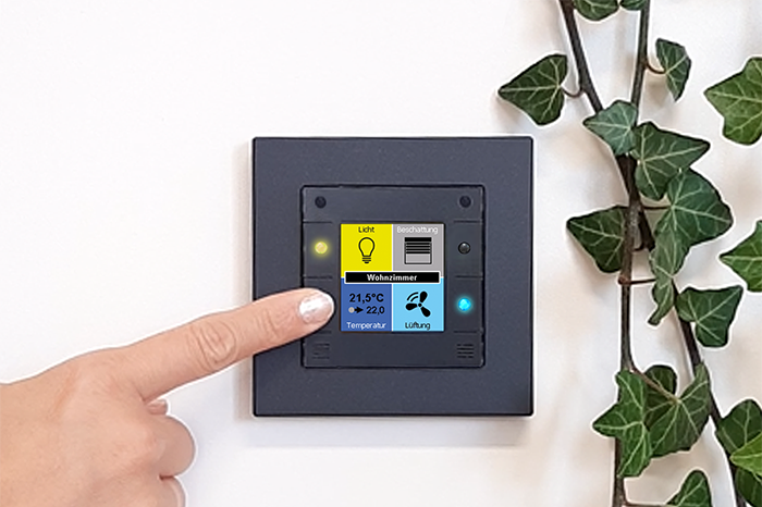
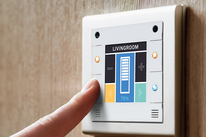
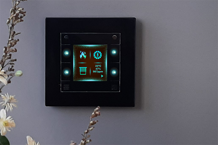
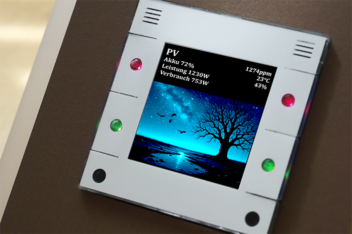
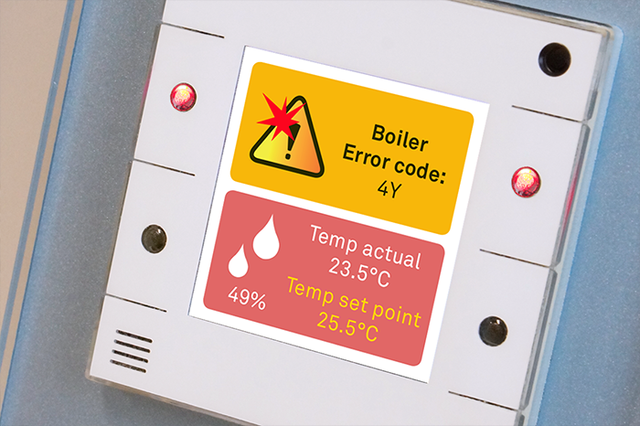
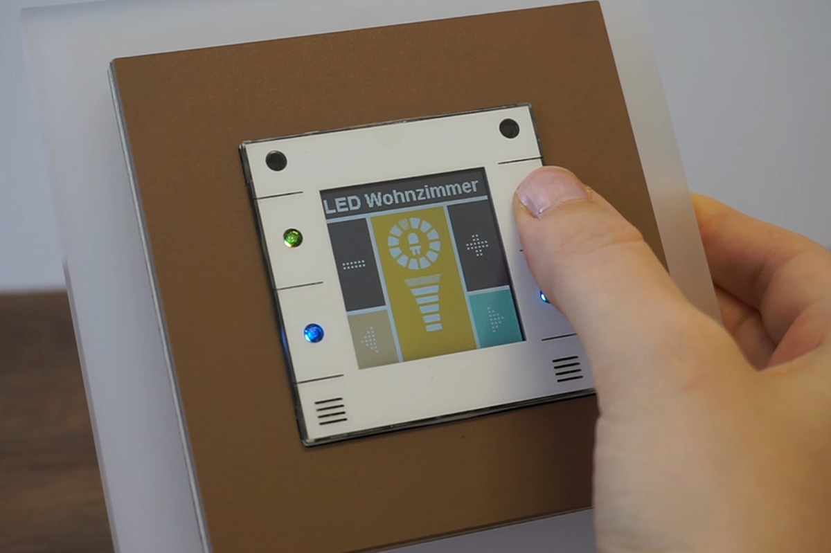
The u::Lux Switch IP is an intelligent control and display unit with four tactile buttons, designed for modern room and building automation. It combines design, sensing, and functionality in a compact device (55×55 mm) and communicates via Ethernet/IP network technology. The u::Lux Switch receives information that is displayed on its color screen and, in turn, sends button actions and sensor values. This allows for intuitive control of lighting, temperature, shading, music, and much more – all through a single, freely configurable device. Available in white, black, and anthracite.
In addition to the IP version, the u::Lux Switch is also available in KNX and digitalSTROM variants.
Typical applications of the u::Lux Switch
- Room and building automation
- Lighting, climate and shading control
- Visualization of measurement data
- Smart Home and IoT integration
- Universal control and information interface
 Advantages of the u::Lux Switch

 How does the u::Lux Switch work?
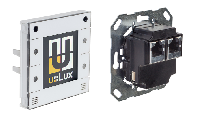
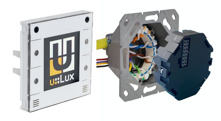
The u::Lux Switch IP communicates via Ethernet network technology. It consists of two parts: a top unit (display and control panel) and a bottom unit (u::Lux NetLink, connection and communication module). The unit fits into a standard 50 mm flush-mounted box (recommended depth: 65 mm).
For operation, the u::Lux Switch only requires an Ethernet network connection to communicate with a control system, embedded PC, or another network participant (e.g. heat pump, heating system, PC, etc.) and to perform the desired control and display functions. In short: the network cable provides both data and power - no additional power line is needed.
The u::Lux Switch is already integrated by several control system manufacturers, so in many cases, our configuration software u::Lux Config is not required or only minimally needed. You can find more information about our partners here.
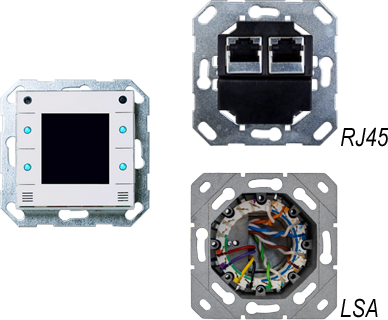
Wiring options
For the u::Lux Switch IP, two connection variants are available depending on your project’s wiring setup: u::Lux Switch RJ45 - for daisy-chain (line) wiring or u::Lux Switch LSA/IDC - for star wiring (PoE).
The u::Lux Switch RJ45 is connected to the control system via Ethernet. All eight wires of the network cable are used — four for data and four for power supply (48 V DC). This allows several u::Lux Switches to be operated in a daisy-chain configuration, with up to 10 devices per line. For power, the system does not use the official PoE standard, but an open 48 V supply system that enables flexible cascading of devices.
Power supply options
u::Lux power components – supply for up to 20 u::Lux Switches:
- u::Lux NetCon Power – 4-port switch, two ports with 48 V power output
- u::Lux NetInj Power – dual injector for power feed-in without switch function
Both devices are powered with 24 V DC (standard control cabinet voltage) and internally generate 48 V DC. Each powered port can supply up to 10 u::Lux Switch RJ45 units, meaning up to 20 devices per unit in total.Alternative: Passive PoE injectorsSo-called passive PoE injectors with a fixed 48 V output can also be used (recommended mainly for testing or single setups). Many inexpensive injectors marketed as “PoE injectors” do not follow the official PoE standard (IEEE 802.3af) but simply apply 48 V DC to the four unused wires of the network cable. The u::Lux Switch RJ45 uses exactly this principle and can therefore be operated with such injectors.Wiring detailsCabling is done using CAT 5e or higher. The RJ45 plug connection makes installation extremely simple and is ideal for line wiring. The u::Lux NetLink RJ45 (the base unit of the u::Lux Switch) contains a genuine 3-port Ethernet switch – two ports for the RJ45 sockets and one internal connection to the display. The system is not PoE in the official sense, since PoE supports only a single powered device and does not allow cascading. In the PoE standard, the power supply is ramped up gradually at startup, and the device reports its power class back to the injector. In contrast, the u::Lux RJ45 system applies 48 V permanently to the four power wires – allowing multiple devices to be operated in series.
The u::Lux Switch LSA/IDC is connected to the control system via Ethernet and powered by a standard PoE switch (minimum Class 1). The connection uses LSA/IDC insulation displacement technology in a star wiring topology. “LSA/IDC” stands for solderless, screwless, and insulation-displacement – a proven technique from network installation in which the wires are simply pressed into color-coded terminals. Termination is done using an LSA/IDC punch-down tool – fast, clean, and permanently reliable. The wiring uses Category 6 (CAT6) or higher installation cables. Each u::Lux Switch LSA has its own dedicated cable directly connected to the PoE switch or PoE injector. This makes the LSA version ideal for classic star-wiring installations in modern buildings.
Power and data transmission
The u::Lux NetLink LSA/IDC (the base unit of the u::Lux Switch) transmits both data and power according to the PoE standard IEEE 802.3af (Class 1). Depending on the PoE equipment used, power can be supplied in two ways:
- Mode A: Data and power are transmitted together over the same four wires.
- Mode B: Data and power are transmitted separately – four wires for data and four for power.
The u::Lux Switch LSA supports both modes, ensuring full compatibility with all standard PoE switches and injectors. The connected PoE device automatically detects the u::Lux Switch and provides the required power. During startup, the voltage is ramped up in a controlled manner while the device reports its power requirements (device class) back to the PoE switch.
Additional sensor connections
In addition, the u::Lux NetLink LSA (base module of the u::Lux Switch) features four extra insulation-displacement terminals for the u::Lux AddOn cable, which allows optional u::Lux sensor modules – e.g. for temperature, humidity, or CO2 – to be connected.
 Expansion Modules – u::Lux AddOns
If required, the u::Lux Switch can be combined with expansion modules for measuring temperature, humidity, and CO2, as well as with a motion detector. In addition, the room control unit—and each of these AddOns—can be expanded with one AddOn-IN2 (digital input module), e.g., for an additional single or double push button. The u::Lux AddOn is connected directly to the base unit of the u::Lux Switch (NetLink) using the supplied cable (length approx. 25 cm).
More information about the u::Lux AddOns is available here.
Any questions?
Just send us an email at office@u-lux.com or call us at +43 662/450351-13. We’re happy to help.
How can I integrate the u::Lux Switch into my project?
The u::Lux Switch IP can be flexibly integrated into a wide variety of control environments – from classic PLC systems to custom software solutions.
Communication is handled via the u::Lux Message Protocol (UMP) – an open, UDP-based protocol that defines all functions of the device. This means any controller or software capable of sending and receiving UDP messages can communicate directly with the u::Lux Switch IP.
u::Lux Message Protocol
UDP-communication
The u::Lux Switch sends and receives UMP messages via UDP port 0x88AC. No TCP handshake, no drivers – communication takes place directly over Ethernet (UDP/IP).
Open data model
Each message contains a header (descriptor) with length, address, and version information, followed by one or more message IDs that carry data or commands. Byte order: Little Endian.
Bidirectional communication
The u::Lux Switch sends events (button presses, sensor values, status changes). The control system sends commands, e.g. to display text or values, change LED colors, or switch pages.
Integration into automation systems
Supported control systems include any platform with UDP capability - already integrated for example alonco, Beckhoff, Comexio, Domiq, evonHOME or Phoenix Contact Emalytics/Niagara. Custom solutions or middleware (e.g. Node-RED, MQTT bridges, JavaScript servers) can also communicate directly with the u::Lux Switch.
The full protocol specification is documented in the u::Lux Message Protocol (UMP). Here’s an example of a typical sequence:
Device startup: The u::Lux Switch sends an InitRequest message. The controller responds with InitResponse and optionally TimeUpdate.
Normal operation:
ID-EditValue / ID-RealValue – Display of values
ID-LED / ID-PageIndex – Display and control functions
ID-Event – Button events
ID-I2C-Temperature – Sensor data
Status reporting: The u::Lux Switch continuously transmits its internal states, which can be processed by the control system.
Status
Status information is transmitted via StateFlags, e.g.:
> Display active/inactive
> Proximity detected
> Sensor values valid
> Error or communication state
These flags allow the control system to respond immediately to status changes.
Benefits of integration
- Open protocol – no license or registration required
- Easy to implement – works with any UDP-capable platform
- fast response times
- Fully documented – all commands, data types, and states are published
- Minimal overhead – extremely efficient UDP communication, ideal for real-time control
- Platform independent – easily integrated with PLCs, Linux servers, Node.js, Python and more...
Need help with integration? If you’d like to integrate the u::Lux Switch into your software solution and have further questions, our software developer will be happy to assist you: a.koenig@u-lux.com
